In the recent past, I’ve talked about how you can create your own custom elements through mash generation, it will be useful to read to understand many aspects of this article.
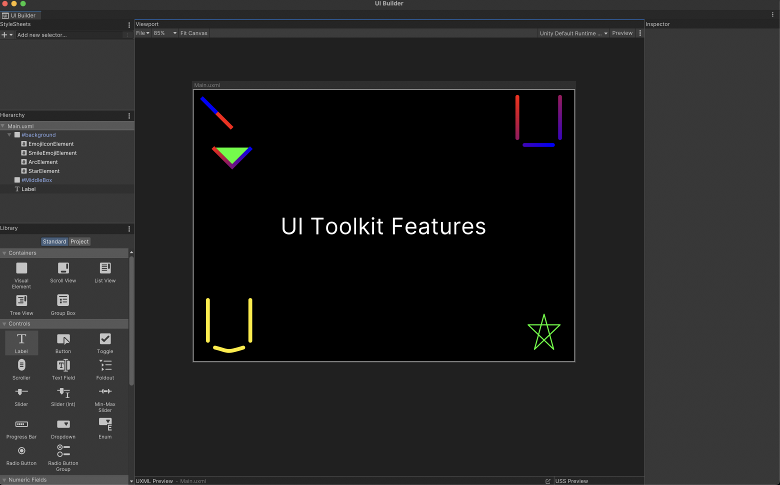
And today, we will be creating custom elements for interfaces, but using the VectorApi in the UI Toolkit of the Unity engine.
After reading this article you will learn:
What is painter2D
How to create elements using it
How to surprise your colleagues with your knowledge of interface creation
Chapter 1: Lines!
Just like in the previous part, we will write our own classes, inheriting from the VisualElement (is the base class for creating a custom interface element) class.
Let’s go from simple to complex, using a code example:
using UnityEngine;
using UnityEngine.UIElements;

namespace CustomElements
{
    public class EmojiIconElement : VisualElement
    {
        public new class UxmlFactory : UxmlFactory<EmojiIconElement> { }

        public EmojiIconElement()
        {
            generateVisualContent += GenerateVisualContent;
        }

        private void GenerateVisualContent(MeshGenerationContext mgc)
        {
            var top = 0;
            var left = 0f;
            var right = contentRect.width;
            var bottom = contentRect.height;

            var painter2D = mgc.painter2D;
            painter2D.lineWidth = 10.0f;
            painter2D.strokeColor = Color.white;
            painter2D.lineJoin = LineJoin.Bevel;
            painter2D.lineCap = LineCap.Round;


            painter2D.BeginPath();

            painter2D.MoveTo(new Vector2((float)(left + (contentRect.width * 0.2)), (float)(top + contentRect.height * 0.1)));
            painter2D.LineTo(new Vector2((float)(left + (contentRect.width * 0.2)), (float)(bottom * 0.7)));

            painter2D.MoveTo(new Vector2((float)(right - (contentRect.width * 0.2)), (float)(top + contentRect.height * 0.1)));
            painter2D.LineTo(new Vector2((float)(right - (contentRect.width * 0.2)), (float)(bottom * 0.7)));

            painter2D.MoveTo(new Vector2((float)(left + (contentRect.width * 0.3)), (float)(bottom * 0.8)));
            painter2D.LineTo(new Vector2((float)(right - (contentRect.width * 0.3)), (float)(bottom * 0.8)));

            painter2D.Stroke();

       }
    }
}
In this case, we will consider the EmojiIconElement class.
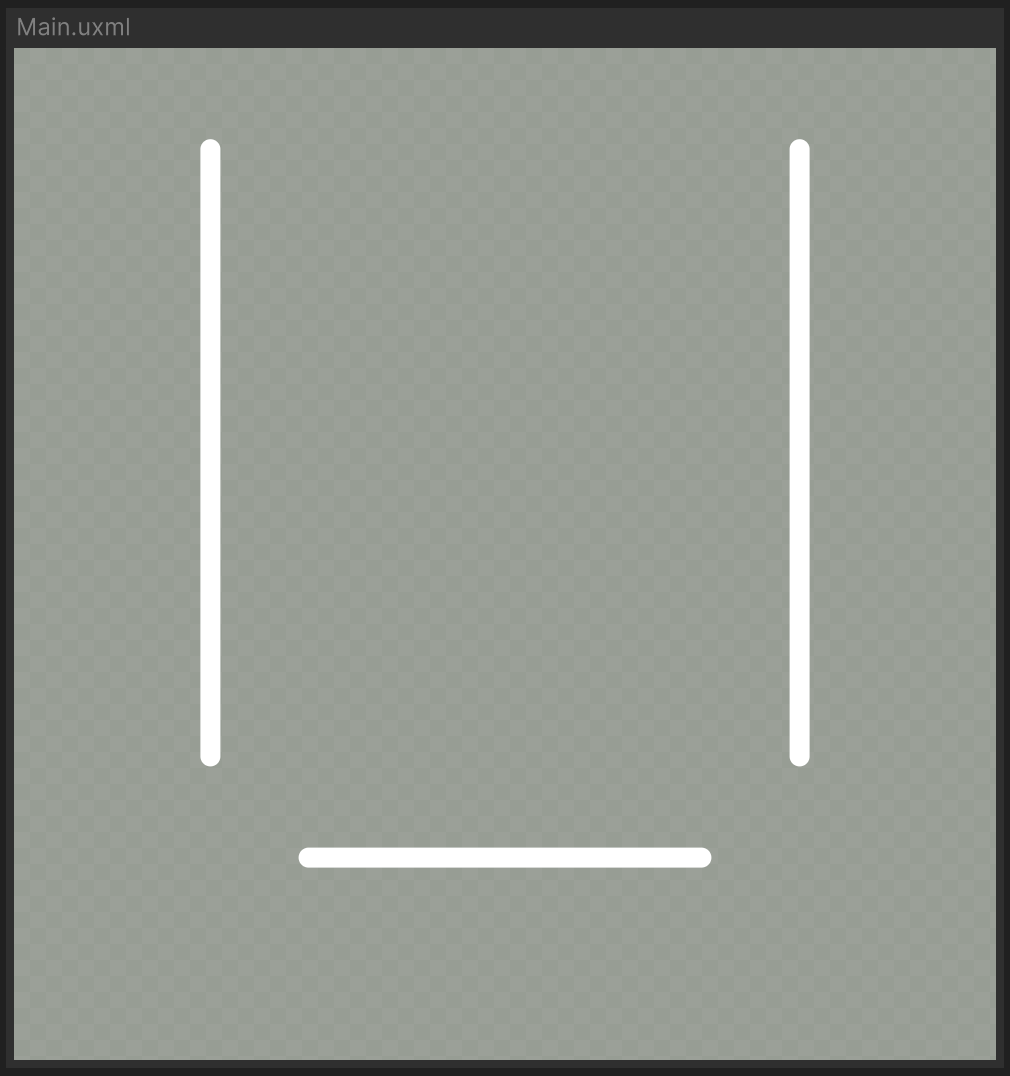
Yes, that’s the interpretation of this smiley face – |_|
Within this chapter, the GenerateVisualContent(...) method and its internals will be covered, and I have already covered the constructor, base class and UxmlFactory in the previous article, in the Mesh and Triangle chapter!
I won’t drag on with the introduction, let’s look at our code.
private void GenerateVisualContent(MeshGenerationContext mgc)
{
    var top = 0;
    var left = 0f;
    var right = contentRect.width;
    var bottom = contentRect.height;

    var painter2D = mgc.painter2D;
    painter2D.lineWidth = 10.0f;
    painter2D.strokeColor = Color.white;
    painter2D.lineJoin = LineJoin.Bevel;
    painter2D.lineCap = LineCap.Round;


    painter2D.BeginPath();

    painter2D.MoveTo(new Vector2((float)(left + (contentRect.width * 0.2)), (float)(top + contentRect.height * 0.1)));
    painter2D.LineTo(new Vector2((float)(left + (contentRect.width * 0.2)), (float)(bottom * 0.7)));

    painter2D.MoveTo(new Vector2((float)(right - (contentRect.width * 0.2)), (float)(top + contentRect.height * 0.1)));
    painter2D.LineTo(new Vector2((float)(right - (contentRect.width * 0.2)), (float)(bottom * 0.7)));

    painter2D.MoveTo(new Vector2((float)(left + (contentRect.width * 0.3)), (float)(bottom * 0.8)));
    painter2D.LineTo(new Vector2((float)(right - (contentRect.width * 0.3)), (float)(bottom * 0.8)));

    painter2D.Stroke();
}
As I said earlier, we are interested in the GenerateVisualContent method.
Briefly, it is activated when our VisualElement needs to display our element or regenerate itself _(this usually happens if there have been changes to the UI element).
The four variables top, left, right, bottom are needed to simplify the handling of positions within our UI element.
It is also important to note that these variable values will change depending on the size of the UI element (in UI Builder / build), and because of this our UI element will scale relative to the size of the screen and the element itself.
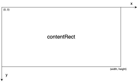
It is on this very contentRect that our generation will take place.
Next we have the description of our painter2D and here we will stop in detail.
In official language, this is a class that allows you to draw vector graphics.
- How exactly do you draw vector graphics?
- Good question!
It provides various API calls that can be used to draw lines, arcs, curves.
Also, it has various properties that affect the result of sketching:
lineWidth - responsible for the line width
strokeColor - stroke color
fillColor - fill color
lineJoin - how the line will look like when connected
lineCap - how the line ends will look like

More clearly how it looks like
We have decided how to prepare our painter2D, now let’s see how paths are handled in graphical programming.
In the context of graphical programming, a “path” is a sequence of geometric shapes such as lines, curves, rectangles and circles that define the shape or contour of an object.
A path can be open or closed.
Open path: Starts and ends with no endpoints connected.
Closed path: The endpoints of a path are connected, forming a closed shape.
Beginning of a new path: This step defines the start of a new vector path. When
BeginPath()is called, you begin writing drawing commands for the new path.Add Drawing Commands: After starting a new path, you add drawing commands, such as
ArcTo(),LineTo(), and others, to create shapes and geometric objects in your path.Path Completion: After you have drawn all the necessary shapes and geometric objects for the current path, you call
ClosePath()to end the path.
This indicates to the graphics engine that you have finished drawing this path and that it should render it.
Let’s now go back to our example and break down what we are doing:
painter2D.BeginPath();

painter2D.MoveTo(new Vector2((float)(left + (contentRect.width * 0.2)), (float)(top + contentRect.height * 0.1)));
painter2D.LineTo(new Vector2((float)(left + (contentRect.width * 0.2)), (float)(bottom * 0.7)));

painter2D.MoveTo(new Vector2((float)(right - (contentRect.width * 0.2)), (float)(top + contentRect.height * 0.1)));
painter2D.LineTo(new Vector2((float)(right - (contentRect.width * 0.2)), (float)(bottom * 0.7)));

painter2D.MoveTo(new Vector2((float)(left + (contentRect.width * 0.3)), (float)(bottom * 0.8)));
painter2D.LineTo(new Vector2((float)(right - (contentRect.width * 0.3)), (float)(bottom * 0.8)));

painter2D.Stroke();
We start with the BeginPath() command, after which we call the MoveTo(Vector2 pos) method - which moves the drawing point to a new position from which the following commands will be executed.
It is followed by the LineTo(Vector2 pos) method, which, as you can understand from the name, draws a straight line from the current painter2D position to the position specified in the method argument.
Next comes two command packs that move the drawing cursor and draw the line.
At the end, we can notice the Stroke() method - which directly draws the outline of the current path we defined earlier.
After calling the method, the current path will be drawn on the canvas using the current stroke style such as line color and thickness.
Congratulations, you now have a custom UI element!
Chapter 2: Curves!
We have two different options for being able to draw curved lines:
The
BezierCurveTo()method generates a cubic Bézier curve from two control points and the final position of the cubic Bézier curve.The
QuadraticCurveTo()method generates a quadratic Bézier curve by a control point and the end position of a quadratic Bézier curve.
Let’s consider their use:
painter2D.BeginPath();
painter2D.MoveTo(new Vector2(100, 100));
painter2D.BezierCurveTo(new Vector2(150, 150), new Vector2(200, 50), new Vector2(250, 100));
painter2D.Stroke();

Bezier curve
And we will also give the code for the second example:
painter2D.BeginPath();
painter2D.MoveTo(new Vector2(100, 100));
painter2D.QuadraticCurveTo(new Vector2(150, 150), new Vector2(250, 100));
painter2D.Stroke();

Quadratic Bézier curve
For a deeper understanding of Bézier curves, we read Wikipedia.
Chapter 3: Arcs!
You can use the following methods to draw arcs:
The
Arc()method creates an arc based on the arc center, radius, and start and end angles provided.The
ArcTo()method creates an arc between two straight segments.
As part of drawing arcs, it’s also worth talking about filling the path.
When at the end of the path we get a closedPath, then we can paint it in some color by calling the painter2D.Fill() method.
Let’s consider an example of building an arc using the Arc() method .
painter2D.lineWidth = 2.0f;
painter2D.strokeColor = Color.red;
painter2D.fillColor = Color.blue;

painter2D.BeginPath();

painter2D.MoveTo(new Vector2(100, 100));


painter2D.Arc(new Vector2(100, 100), 50.0f, 10.0f, 95.0f);
painter2D.ClosePath();


painter2D.Fill();
painter2D.Stroke();
And painter2D.FillColor will define fill color.
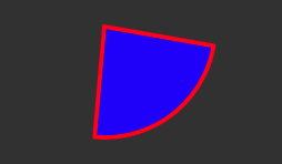
Red outline and blue fill.
Using painter2D.ArcTo(), we can draw a curve:
painter2D.BeginPath();
painter2D.MoveTo(new Vector2(100, 100));
painter2D.ArcTo(new Vector2(150, 150), new Vector2(200, 100), 20.0f);
painter2D.LineTo(new Vector2(200, 100));
painter2D.Stroke();

Curve through arc
You may have wondered if you can use the Arc() method to draw a circle or a pie chart.
– Well, of course you can
Just check documentation from Unity.
Chapter 4: The rest?
Here I want to cover some stuff that didn’t make it into the other chapters, and some other comments on drawing.
The first thing I want to talk about is holes in fills.
When you call Fill() to fill an area contained within a path, you can also create “holes” in that filled area using additional subpaths.
To create a hole, you must create an additional subpath using MoveTo(), and then use a fill rule to determine which areas get filled and which don’t.
Here are the two basic fill rules:
OddEven: Draw a ray from the given point to infinity in any direction, and count the number of intersections with path segments. If the number of intersections is odd, the point is considered inside the path, if the number of intersections is even, the point is considered outside.
NonZero: Draws a ray from the given point to infinity in any direction, and counts the intersections of the path segments. When segments intersect the ray from right to left, the counter is decremented, and when segments intersect the ray from left to right, the counter is incremented. If the counter is zero, the point is considered outside the path, otherwise, it is considered inside.
So you can use these rules to create a hole in a filled area by defining a subpath that defines the outline of the hole, and using a fill rule to specify how the areas should be filled.
The code above creates a rectangle with an additional subpath that defines a diamond shape inside the rectangle. This diamond will be the “hole” in the filled area of the rectangle.
painter2D.BeginPath();
painter2D.MoveTo(new Vector2(10, 10));
painter2D.LineTo(new Vector2(300, 10));
painter2D.LineTo(new Vector2(300, 150));
painter2D.LineTo(new Vector2(10, 150));
painter2D.ClosePath();

painter2D.MoveTo(new Vector2(150, 50));
painter2D.LineTo(new Vector2(175, 75));
painter2D.LineTo(new Vector2(150, 100));
painter2D.LineTo(new Vector2(125, 75));
painter2D.ClosePath();

painter2D.Fill(FillRule.OddEven);
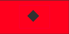
Rectangle with a holes;
Second, it is possible to customize styles in each subpath.
To do this, you need to use the BeginPath() and ClosePath() methods and change the values in painter2D between them.
private void GenerateVisualContent(MeshGenerationContext mgc)
{
    var painter2D = mgc.painter2D;
    painter2D.lineWidth = 10.0f;

    // First subpath starts
    painter2D.BeginPath();
    painter2D.strokeColor = Color.red;

    painter2D.MoveTo(new Vector2(50, 50));
    painter2D.LineTo(new Vector2(100, 100));

    painter2D.Stroke();
    painter2D.ClosePath();
    // End of first subpath

    // Second subpath starts
    painter2D.BeginPath();
    painter2D.strokeColor = Color.blue;

    painter2D.MoveTo(new Vector2(20, 20));
    painter2D.LineTo(new Vector2(60, 60));

    painter2D.Stroke();
    painter2D.ClosePath();
    // End of second subpath

    // Third subpath starts
    painter2D.BeginPath();
    painter2D.strokeGradient = new Gradient()
    {
        colorKeys = new GradientColorKey[]
        {
            new() { color = Color.red, time = 0.0f },
            new() { color = Color.blue, time = 1.0f }
        }
    };
    painter2D.fillColor = Color.green;

    painter2D.MoveTo(new Vector2(50, 150));
    painter2D.LineTo(new Vector2(100, 200));
    painter2D.LineTo(new Vector2(150, 150));

    painter2D.Fill();
    painter2D.Stroke();

    painter2D.ClosePath();
    // End of subpaths
}
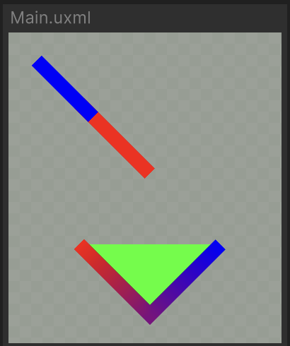
Three different styles.
An attentive viewer has already noticed the next feature – support for gradients for strokes.
painter2D.strokeGradient = new Gradient()
{
    colorKeys = new GradientColorKey[]
    {
        new() { color = Color.red, time = 0.0f },
        new() { color = Color.blue, time = 1.0f }
    }
};
Using the strokeGradient property you can draw a stroke through a gradient.
Chapter 5: Conclusion
Congratulations on reading this article to the end.
Today we figured out how to draw custom elements in interfaces, what tools are available for this in the Unity engine.
For a deeper dive and study of creating interface elements, I recommend the official documentation.
If you have any questions or did not understand some part, write in the comments, I will try to explain what and how :)
Thank you for your attention and see you soon